Wheel collection
Wheels. Built your way.
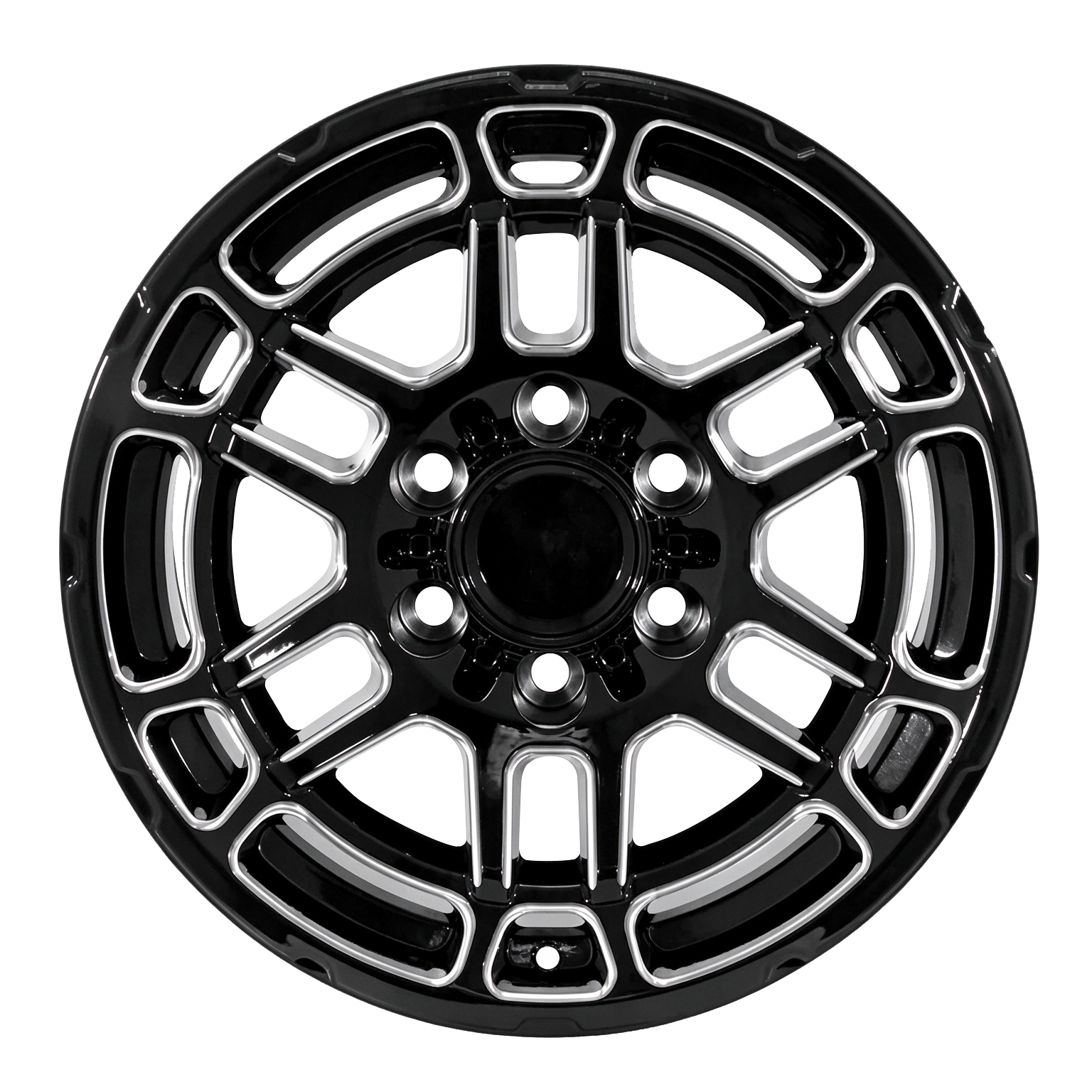
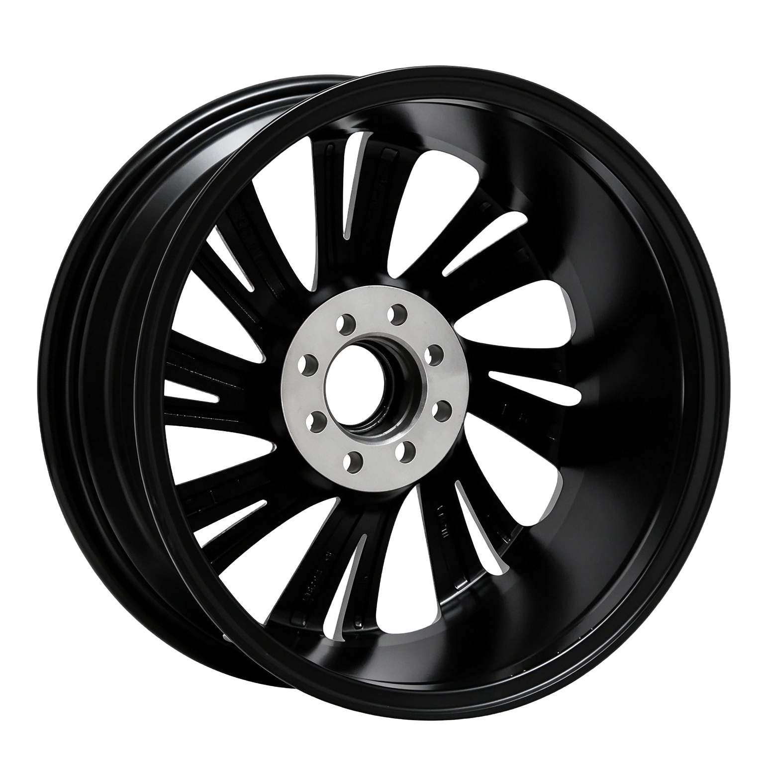
From one-piece forged performance wheels to two-piece custom configurations, ROOVA helps brands and distributors translate a design brief into a production-ready wheel specification.
Explore the range01 / 03

01 / 03


Precision drives further.
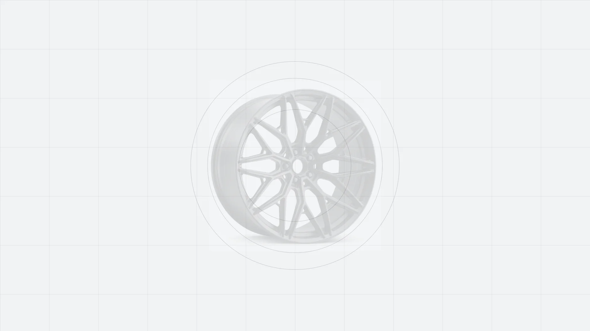
Custom engineered
Your custom wheel journey.
From idea to road-ready performance, made for your vehicle.
 01
Choose Your Style
Explore forged wheel styles or share your inspiration.
 02
Confirm Specifications
Confirm size, PCD, offset, center bore and finish.
 03
Receive Your Design
ROOVA prepares a detailed wheel drawing for approval.
 04
Precision Manufacturing
Your custom wheels are CNC-machined and quality checked.
 05
Worldwide Delivery
Secure packaging and global shipping to your destination.
Controlled manufacturing
Production process.
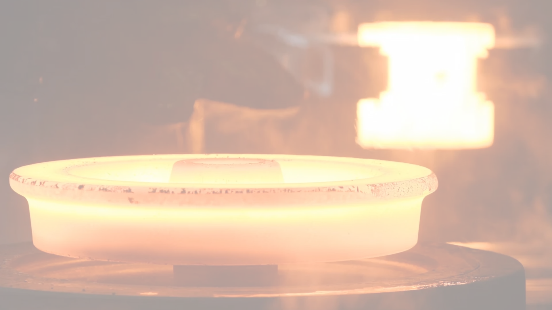
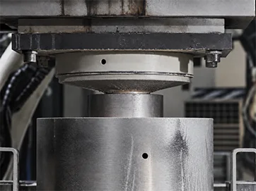
FORGING
Every wheel begins as a solid aluminium alloy billet. The billet is loaded into a forging press and squeezed under immense pressure, which compacts the grain structure of the metal: its molecular density rises sharply and spreads evenly across a far larger area. The material therefore gains strength and impact resistance while shedding weight at the same time, and the rough outline of the wheel disc has already taken shape.
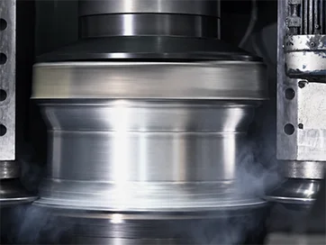
FLOW FORMING
The forged blank leaves the press as a flat disc, but a wheel also needs its outer section — the rim. A flow-forming machine grips the edge of the disc and rolls it outwards under pressure, drawing the metal into a hollow cylinder. Because the rim is squeezed a second time at this stage, its density climbs once more and the finished wheel ends up noticeably stronger.
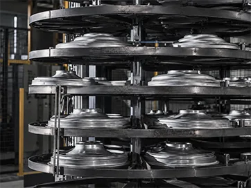
HEAT TREATMENT
The wheel then passes through a heat treatment cycle at temperatures between 200 and 500 degrees Celsius. This redistributes the internal structure of the metal so that it becomes more uniform and stable, relaxing the internal stress left behind by forging and cold working. Elasticity is restored, and both the strength of the aluminium alloy and its resistance to impact are raised.
LATHE CUTTING
On the lathe, cutting tools work the rim surfaces down to their final dimensions. Material is removed from the rim area to give the wheel the profile called for by its design, and to bring every critical dimension within the tolerances demanded by the required specification.

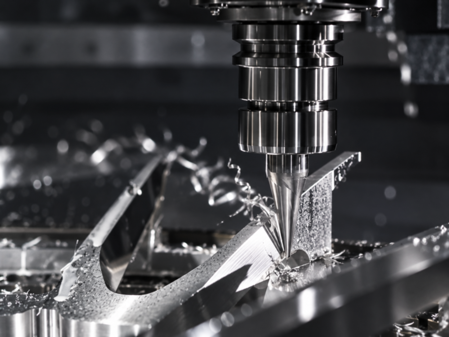
MILLING
Milling gives the disc its finished appearance: the number of spokes and the fine detailing of the wheel design are all cut at this stage, exactly as defined in the approved drawing. A one-piece (monoblock) design demands a greater cutting volume and deeper tool travel, so these programmes are run on more capable equipment such as a 4-axis or 5-axis milling machine.
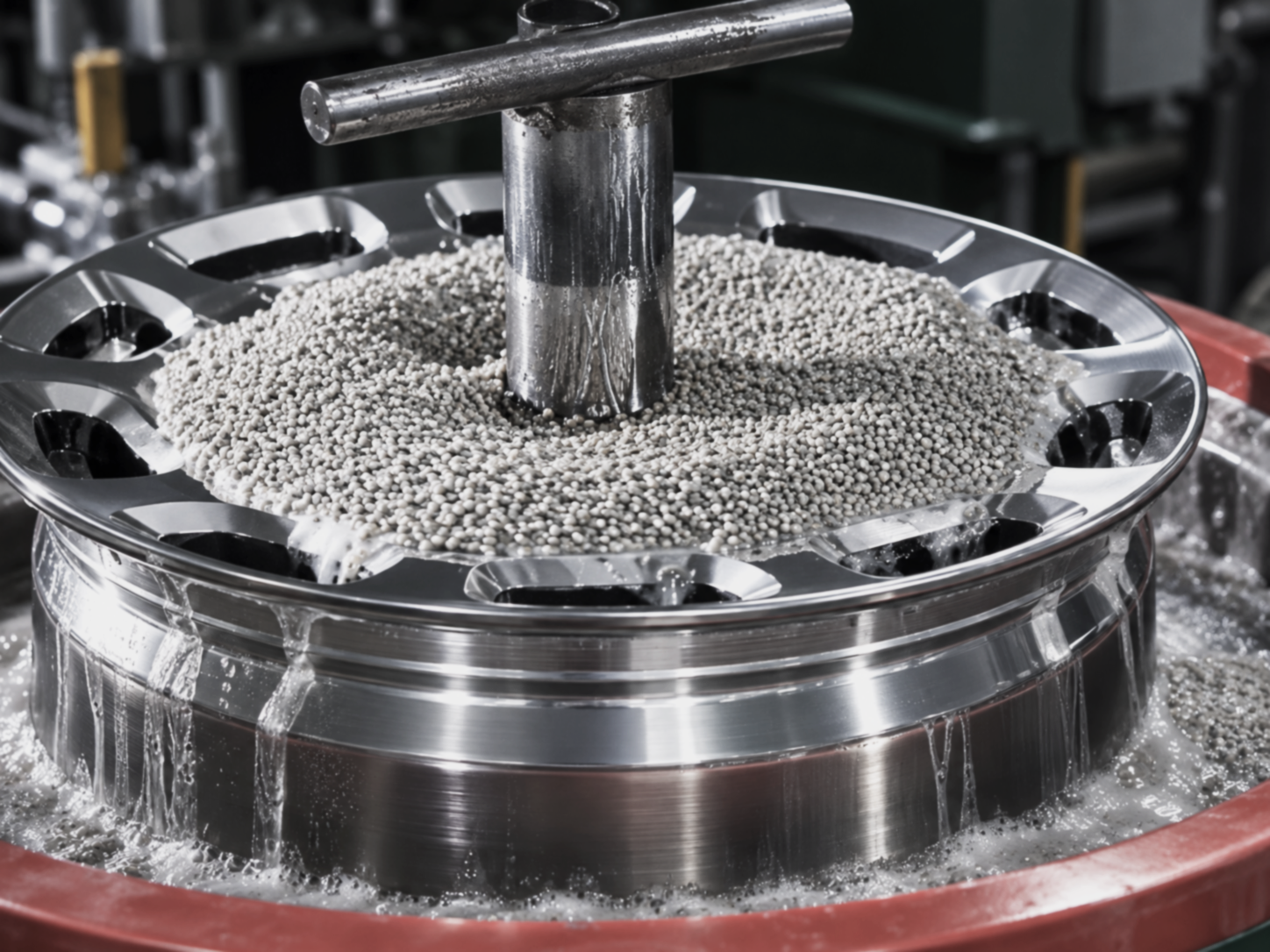
GRINDING AND POLISHING
Once the wheels have been painted, they are ground and polished to bring out the full depth and perfection of the paint finish. The same stage is also used to verify the quality of the spray work. Every wheel is inspected continuously along the way, which is what allows each one to reach the customer in the best possible condition.
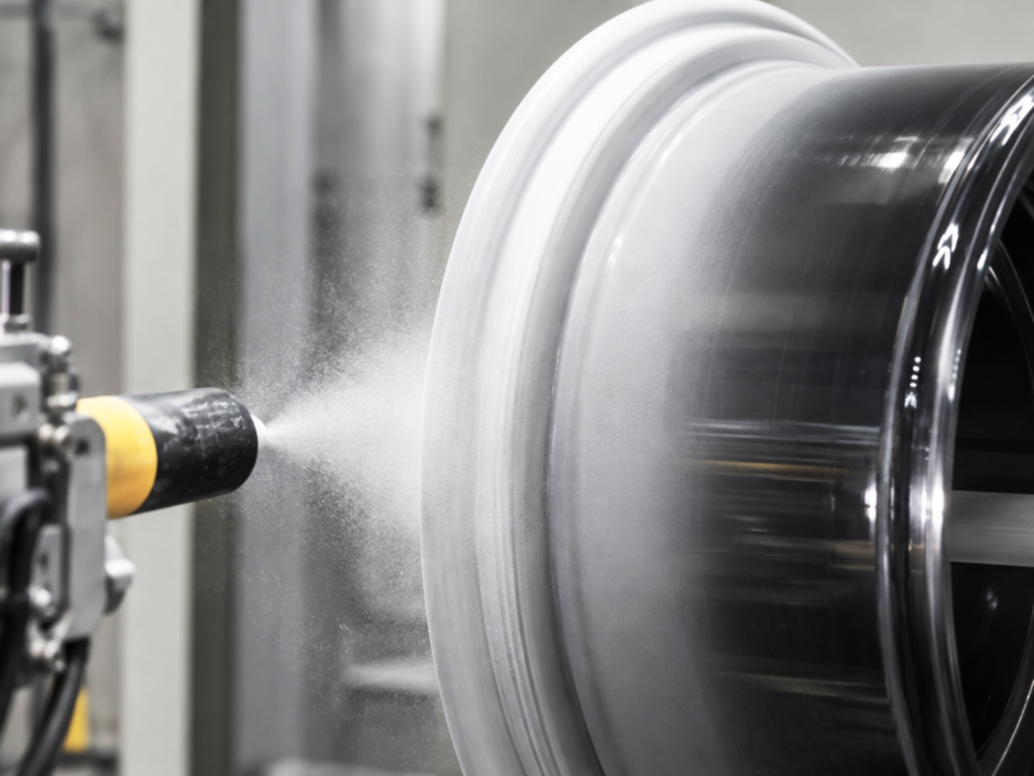
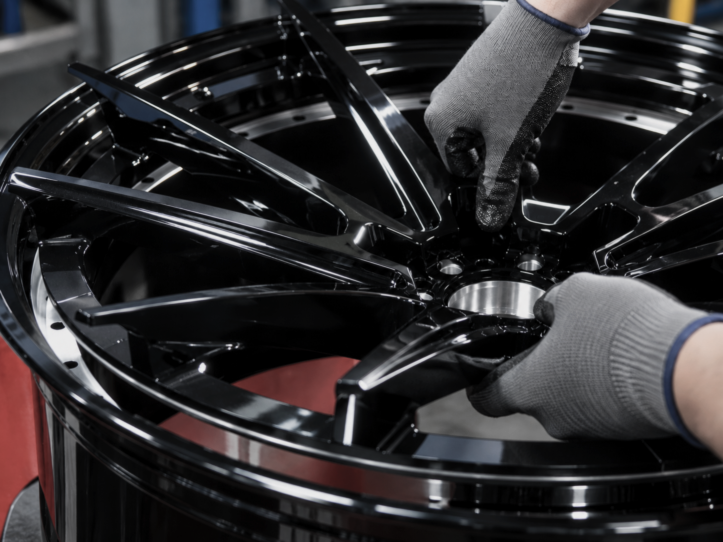
PAINTING, ASSEMBLY
Final assembly takes place in this area: fitting the valve stem, mounting the centre cap, and joining the halves of a two-piece wheel. Every screw on a two-piece wheel is tightened by hand with the help of a torque wrench, so that all of them carry an identical load and none is overlooked. Each fastener is then marked so that any loosening can be spotted during later inspection, and the torque wrenches themselves are recalibrated on a regular schedule.
PACKAGING AND ASSEMBLY
With manufacturing complete, the wheel moves to packing and dispatch. The first step is to cover the face of the disc with a protective cloth, which keeps the surface free from damage in transit. Cushioning material is then placed inside the box, since proper shock absorption in the carton is what ultimately protects the wheel on its journey.
RADIAL FATIGUE TEST
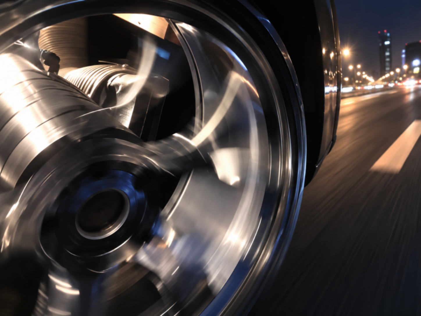
This test measures how well a wheel stands up to heavy loads applied in the radial direction, and whether repeated loading eventually causes metal fatigue. It runs on a test rig that reproduces the way a wheel rotates on an ordinary road surface.
WHEEL CORNERING FATIGUE TEST
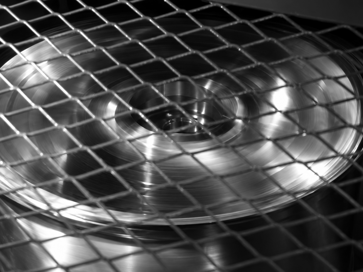
Here the load is applied from the side rather than the top, establishing how much lateral force the wheel can carry before repeated cycles begin to fatigue the metal. As with the radial test, the equipment simulates a wheel turning on an ordinary road surface.
IMPACT TEST MACHINE
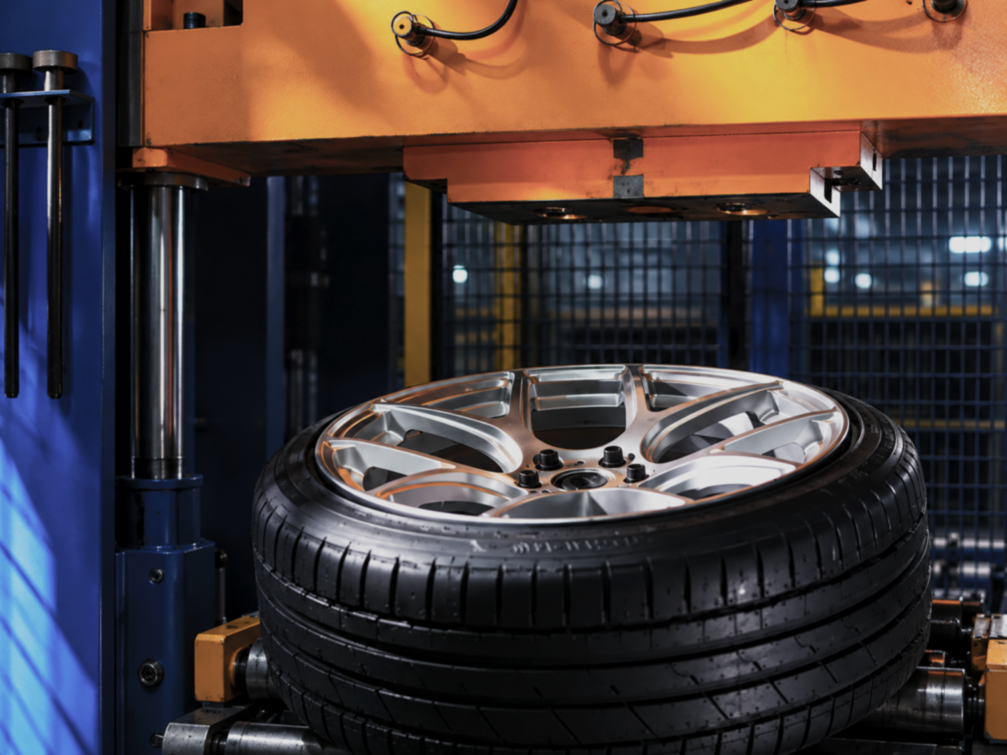
The impact rig reproduces the conditions a wheel meets on the road and assesses how it copes with a sudden blow, such as striking a pothole or a kerb. Any crack running through the material, or any loss of tyre pressure caused by the impact, is recorded during the test.
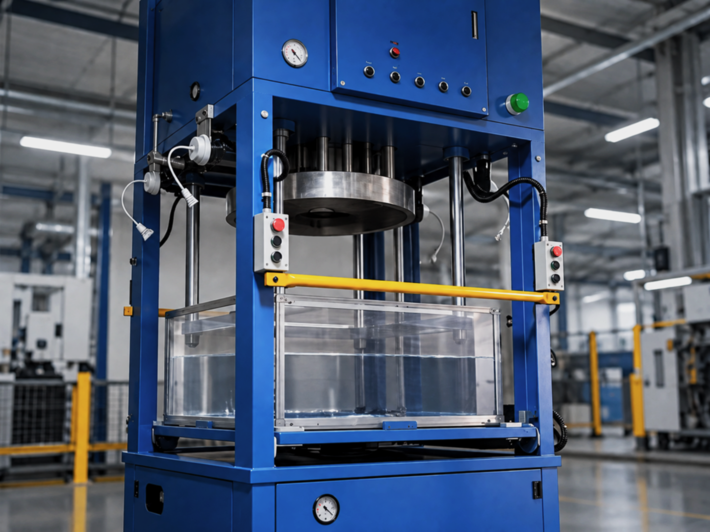
IMMERSION LEAK TEST MACHINE
This test exists to catch any air leak around the valve stem. The wheel is lowered into a water tank while high pressure air is fed through the valve, and the water surface is watched closely: any escaping bubble immediately reveals a leak.