
Suspension product category
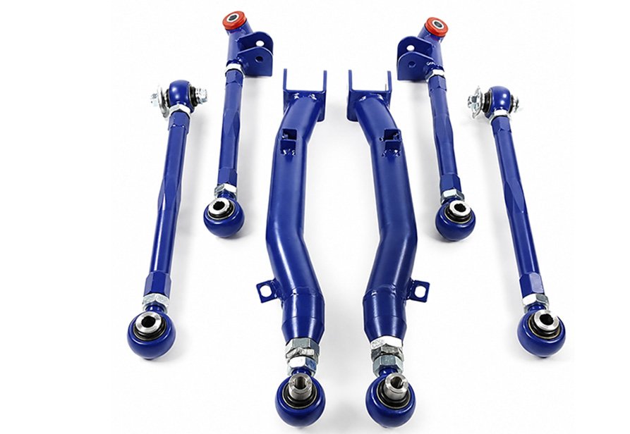
Adjustable Control Arm Kits
Restore camber, toe and suspension geometry after lowering or chassis modification.
View more
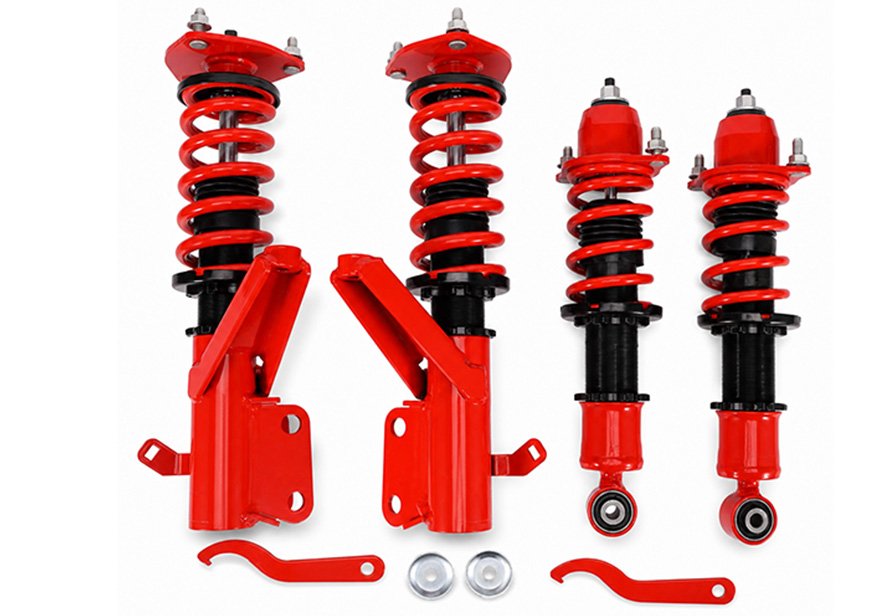
Coilovers, dampers, springs and chassis service parts selected around verified fitment, intended use and measurable setup targets.
Explore the range01 / 03

Suspension product categories
Choose a category first. Vehicle-specific applications and specifications open only when you want to see more.
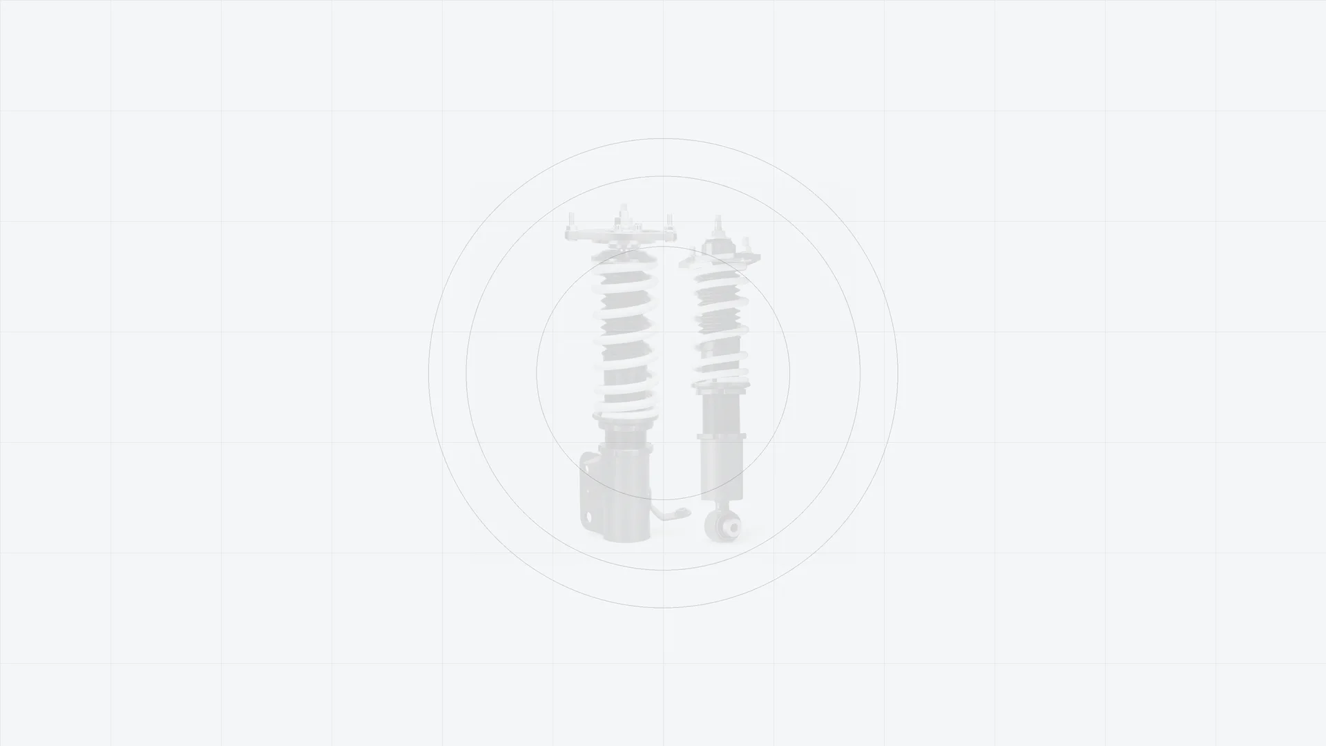
Custom engineered
Built around your vehicle, driving style and performance goals.
 01
Provide your vehicle make, model, year, and intended use — Street, Track, Drift, Off-Road, or Stance.
 02
Define key specifications, including front and rear axle loads, desired ride height, spring rates, damping adjustment, top mount configuration, and mounting dimensions.
 03
ROOVA will develop a recommended suspension setup and provide detailed specification drawings for your review and approval before production begins.
 04
Custom springs, dampers, and top mounts are precisely assembled to your specifications and undergo comprehensive quality inspection and performance testing.
 05
Your custom coilover system is securely packaged and shipped worldwide, with professional installation guidance and after-sales support available.
Controlled manufacturing
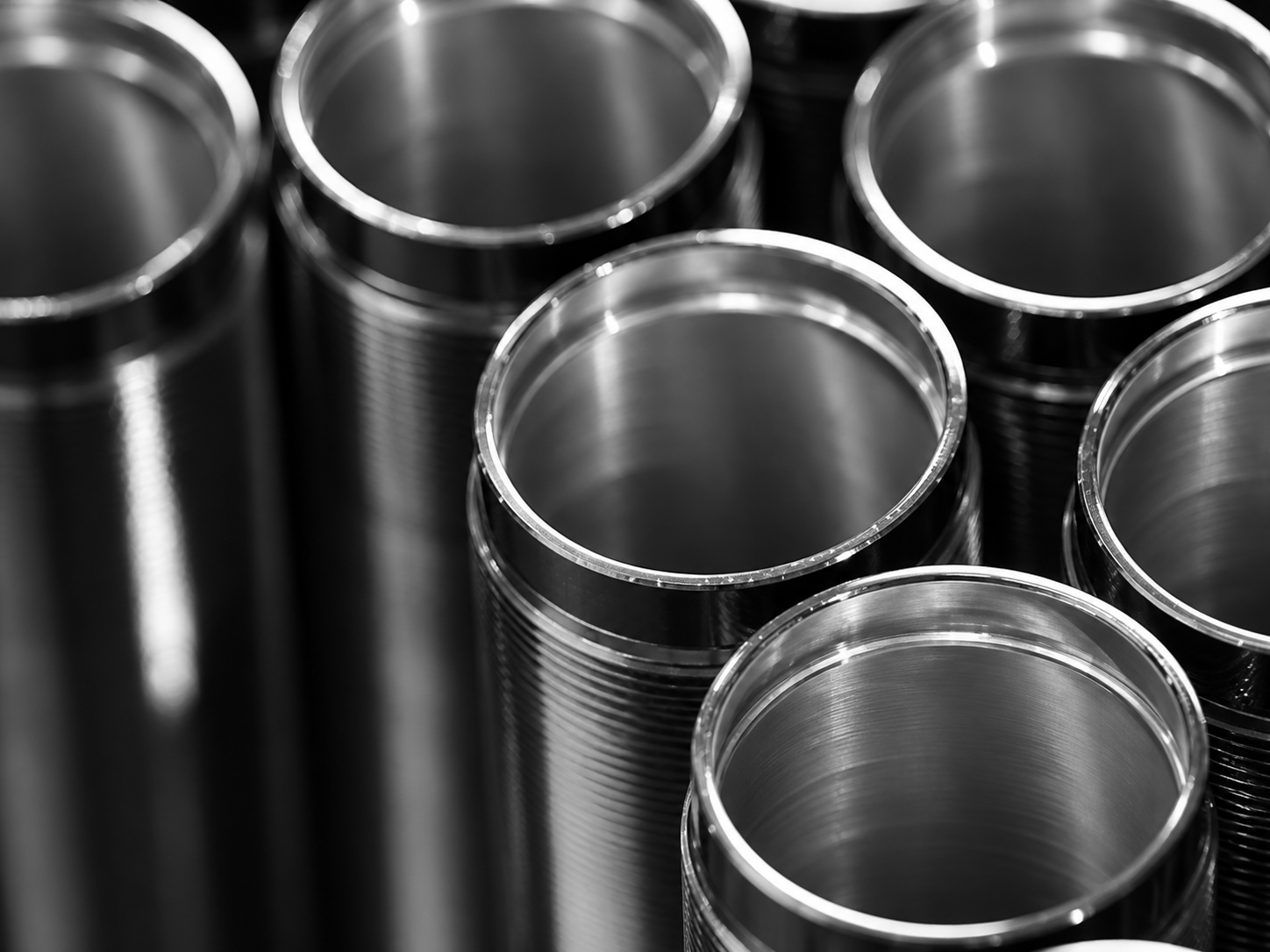
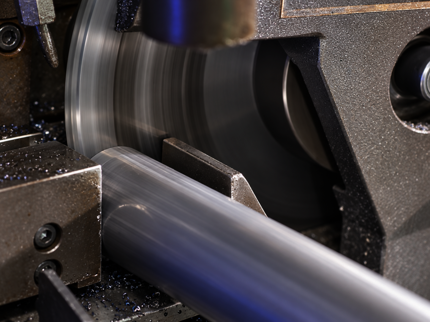
Damper bodies are turned from steel tubing on CNC lathes — outer diameter, end faces and adjustment threads to the drawing — then the cylinder bore is finished by internal turning. Chips and cutting-fluid residue are cleared, and bore size, thread and end faces are checked before the parts go forward to welding and coating.
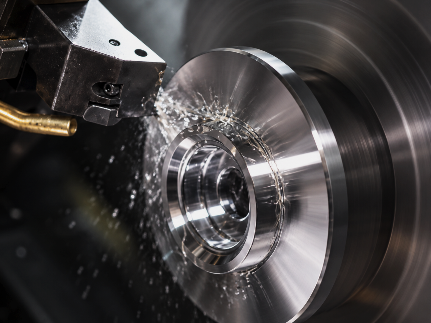
Aluminium spring seats, upper mounts and locking collars are batch-turned, with face, bore, step and thread features cut in sequence. The seating face and adjustment thread are held to the drawing so the seat locates squarely on the body and the collar adjusts smoothly. Parts are deburred, cleaned and batch-identified.
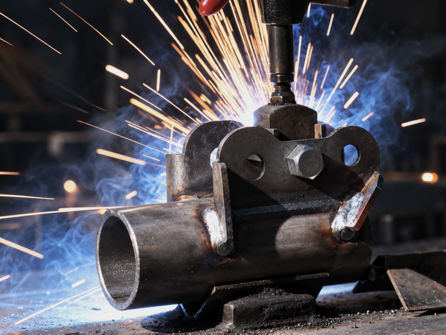
Steel brackets are formed and joined to the damper body. The joint is locally flame-heated as the process requires, then welded under fixture positioning and controlled parameters. The weld is cleaned and checked for quality, position and alignment before the assembly moves on.
Adjustment collars, rings and other exposed steel parts are rack plated: hung on jigs, degreased, activated and chrome plated so the adjustment features come out bright and wear-resistant. Thickness and appearance are checked, and threads are protected so adjustment stays free after plating.

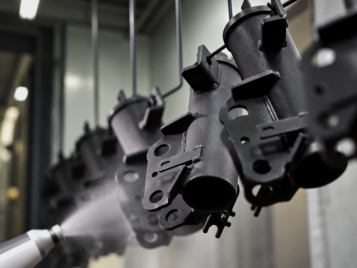
Welded bodies and brackets are hung on a conveyor coating line, pre-treated, coated and cured for uniform corrosion protection and a consistent finish. Threads, bores and mating surfaces are masked as required, and coverage and appearance are checked after curing.
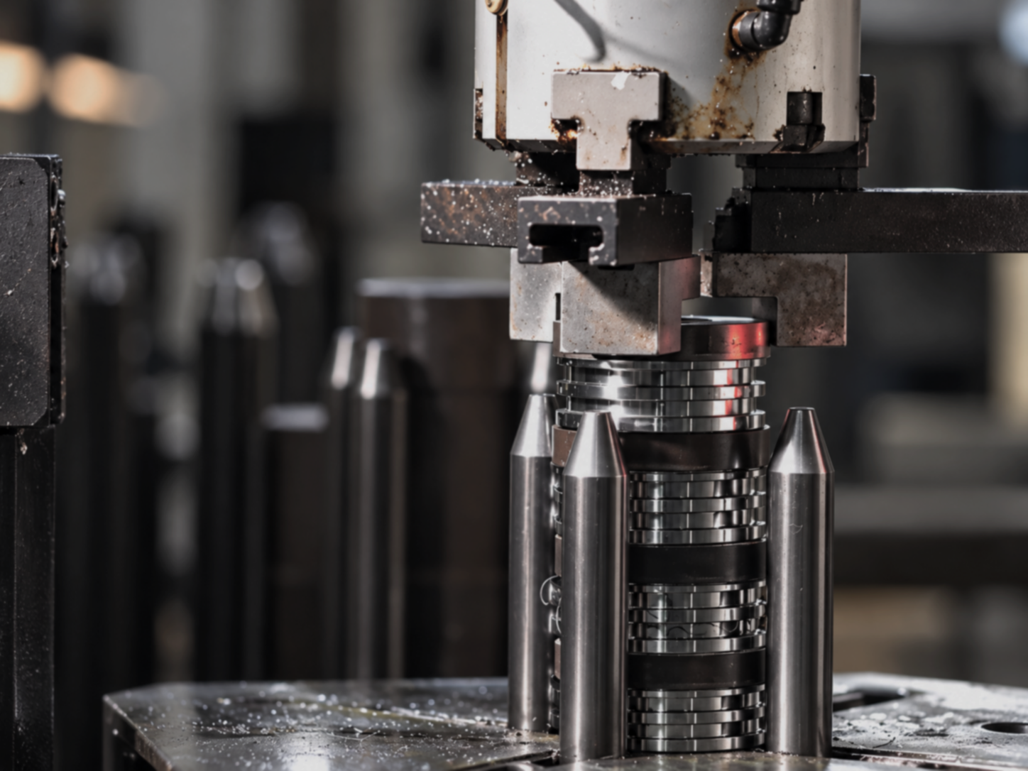
Pistons, valve shims, rod guides and seals are assembled under controlled cleanliness. The shim stack is arranged in the specified sequence and pressed into position with a press and locating pins, so that the stack seats squarely and the seal elements are not damaged. Component orientation, shim sequence and pressing position are confirmed unit by unit.
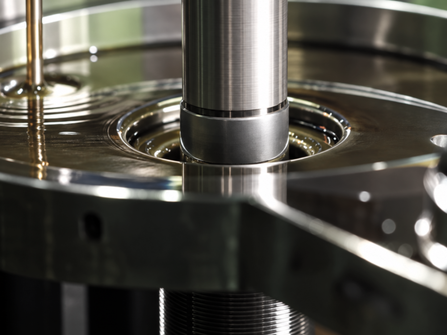
The damper is filled with the specified oil through a metered nozzle. Oil is delivered to the required level and air is allowed to escape before the unit is closed, with fill volume held to the product specification. Seal and guide areas stay clean and lubricated throughout.

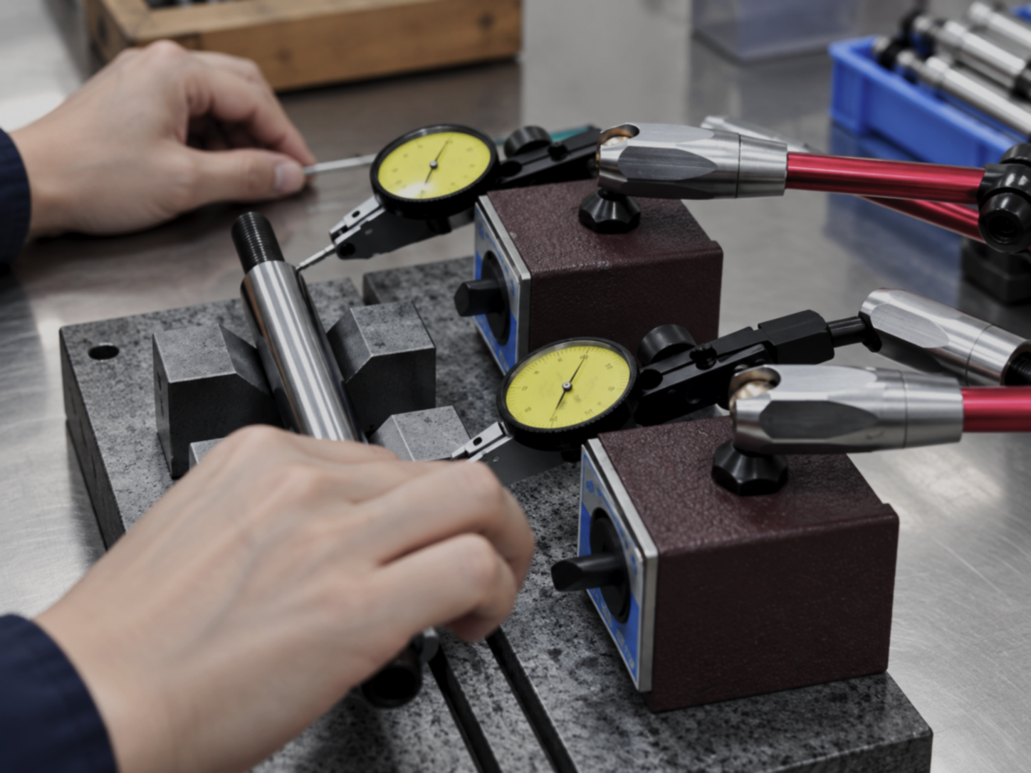
Piston rods are gauged on a surface bench with dial indicators on magnetic stands. The rod is supported and turned to read radial runout along the working length, so straightness and roundness are verified rather than assumed. Diameter and the condition of the finished surface are checked at the same time.
The rod is inserted through the guide and seal assembly with its working surface lubricated, so the seal lip is not damaged and the rod moves freely. Seating and free movement are confirmed before the unit is closed.
Coated bodies are inspected and racked ahead of final assembly. Threads, bores and machined faces are protected through handling and storage, and bodies stay batch-identified. Springs, seats and mounting components are fitted at the assembly stage to complete the coilover unit.