
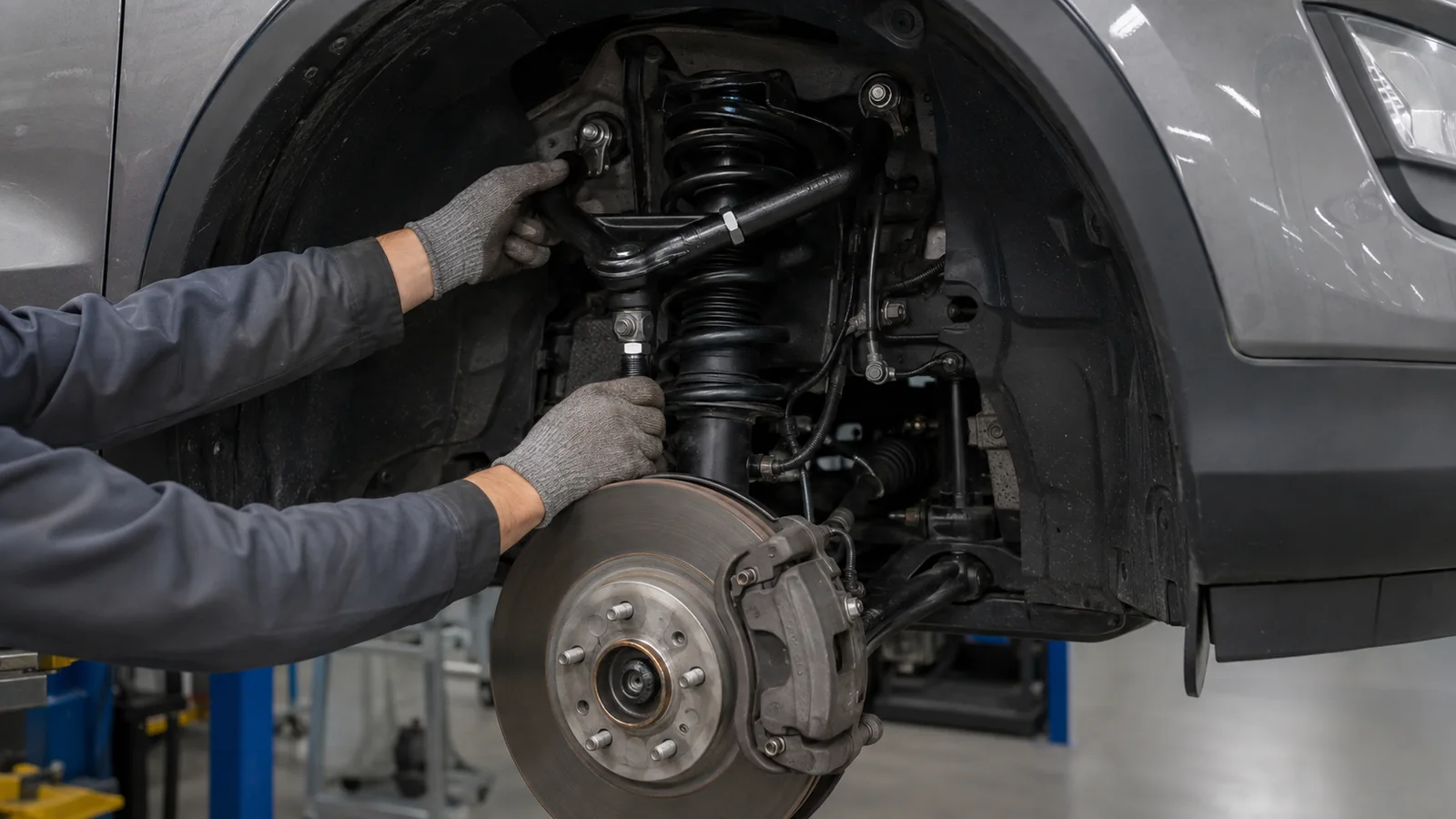
Changing the ride height of an SUV can affect more than its stance and ground clearance. Depending on the suspension layout, raising or lowering the vehicle may also change camber, caster, toe and the working position of surrounding suspension components.
For touring, street-performance and modified SUV applications, an adjustable control arm kit provides a way to introduce additional suspension geometry adjustment where the original components may offer limited correction.
ROOVA approaches adjustable suspension arms as part of the complete vehicle setup rather than as isolated replacement components.
The following application scenario illustrates how an adjustable control arm package can be planned around ride-height changes, alignment requirements, component clearance and real-world vehicle use.
The Challenge: Restoring Alignment After a Ride-Height Change
Consider a typical SUV that has been modified from its original ride height.
The customer wants the new stance or additional clearance provided by the suspension setup, but the change in suspension position can also influence wheel alignment.
Depending on the vehicle and suspension design, the resulting geometry may move outside the preferred adjustment range available with the original control arms.
This can create several practical concerns:
- Camber that cannot be corrected sufficiently with the original adjustment
- Caster changes that affect steering behavior
- Toe changes following suspension-height adjustment
- Uneven tyre wear
- Reduced alignment flexibility
- Clearance issues between suspension components
- Difficulty achieving a balanced left-to-right alignment
The objective is therefore not simply to replace the original arms with adjustable versions.
The purpose of the adjustable control arm kit is to provide a usable range of geometry correction while maintaining appropriate fitment, clearance and component operation for the intended vehicle application.
Vehicle and Suspension Inputs
Development begins by understanding the vehicle configuration and the reason additional adjustment is required.
Depending on the application, relevant project inputs may include:
- Vehicle make, model and generation
- Front or rear suspension layout
- Original and modified ride height
- Existing spring, coilover or lift configuration
- Wheel and tyre specifications
- Current alignment condition
- Desired camber, caster or toe correction
- OE mounting-point configuration
- Clearance around the chassis, wheel, tyre and other suspension components
- Intended daily, touring, performance or mixed-road use
- Installation and service requirements
These inputs establish the working envelope for the adjustable arm rather than assuming that maximum adjustment is automatically the best solution.

Why Ride Height Can Affect Suspension Geometry
Control arms determine how the wheel and hub assembly move relative to the chassis.
When vehicle ride height changes, the suspension no longer operates from exactly the same static position as the original configuration.
Depending on the suspension design, this can influence wheel alignment parameters such as camber, caster and toe.
The amount and direction of change vary by vehicle. This is why an adjustable suspension arm should be developed around a defined vehicle application rather than treated as a universal correction component.
For a modified SUV, the engineering question becomes:
How much additional adjustment is useful, and how can that adjustment be introduced without creating new fitment or clearance problems?
Engineering an Adjustable Control Arm Kit
An effective adjustable control arm needs to balance geometry correction, mechanical strength, adjustment accessibility, joint movement, clearance and serviceability.
These requirements interact with one another.
Increasing the available adjustment range can change the working position of the arm. Changing arm geometry can affect clearance. Changing joint or bushing configuration can influence movement, noise and maintenance requirements.
ROOVA therefore reviews the adjustable control arm as part of the complete suspension system.
Camber Adjustment
Camber describes the inward or outward inclination of the wheel when viewed from the front or rear of the vehicle.
After a ride-height change, some suspension layouts may produce more positive or negative camber than desired. If the OE adjustment range is insufficient, an adjustable control arm can provide an additional method of repositioning the wheel carrier relative to the chassis.
The objective is not to create the largest possible camber range.
For a street or touring SUV, the more useful goal is to provide sufficient adjustment to support the intended alignment while retaining appropriate component engagement, clearance and suspension movement.
This is particularly relevant where tyre life, predictable road behavior and alignment consistency are priorities.
Caster and Suspension Position
On applicable front suspension designs, control-arm geometry may also influence caster.
Caster affects the relationship between the steering axis and the road surface and can influence steering return, straight-line behavior and steering feel.
When ride height, tyre size or suspension configuration changes, additional caster adjustment may be useful for some applications.
However, increasing caster or repositioning a control arm can also change the location of the wheel within the wheel arch and alter clearance to surrounding components.
For this reason, caster correction cannot be considered independently from:
- Tyre diameter
- Wheel offset
- Wheel-arch clearance
- Steering lock
- Suspension travel
- Brake-line and sensor routing
- Other suspension components
A useful adjustable arm therefore needs to provide geometry correction within the physical limits of the vehicle.
Toe Correction Where Applicable
Depending on the suspension layout, adjustable links or control arms may also be used to influence rear or front toe.
Toe can change as suspension position changes, and an appropriate toe setting is important for tyre wear, straight-line stability and vehicle response.
For applications requiring additional toe correction, the adjustable component needs to provide a practical adjustment range while maintaining secure locking and appropriate joint alignment.
As with camber and caster, the objective is controlled correction rather than adjustment for its own sake.
Adjustment Range vs. Component Integrity
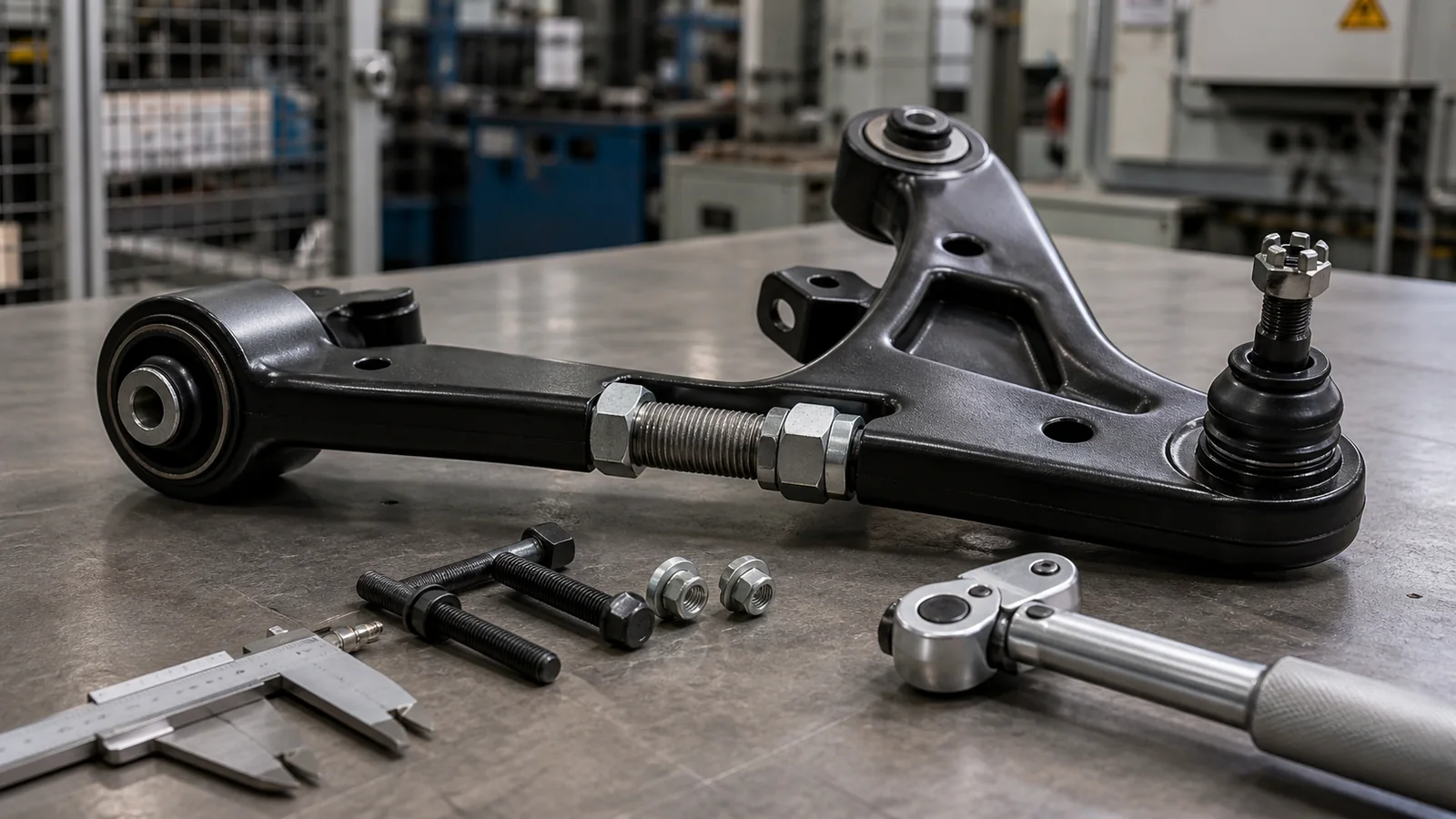
One of the most important decisions in an adjustable control arm is how the adjustment mechanism is designed.
A large advertised adjustment range may appear attractive, but maximum range alone does not define a well-engineered component.
At different adjustment positions, the arm must still maintain appropriate:
- Thread engagement
- Locking security
- Joint position
- Component clearance
- Suspension articulation
- Installation accessibility
- Structural load path
For this reason, ROOVA treats the usable adjustment range as more important than simply maximizing the published adjustment figure.
The product needs to provide the correction required for the intended vehicle setup while remaining within the defined mechanical operating range.
Joint and Bushing Considerations
The connection points of an adjustable suspension arm influence both movement and vehicle behavior.
Depending on the product application, the arm may use bushings, spherical-type joints or another specified joint configuration.
Each approach has different considerations for:
- Articulation
- Compliance
- Noise and vibration
- Maintenance
- Environmental exposure
- Installation
- Intended road or performance use
For a touring or street-focused SUV, component selection should reflect the intended balance between geometry control, durability, serviceability and everyday usability.
A component designed for maximum directness in a competition application may not necessarily provide the characteristics expected from a daily-driven or long-distance touring vehicle.
The intended use case therefore remains part of the product specification.
Clearance Through Suspension Movement
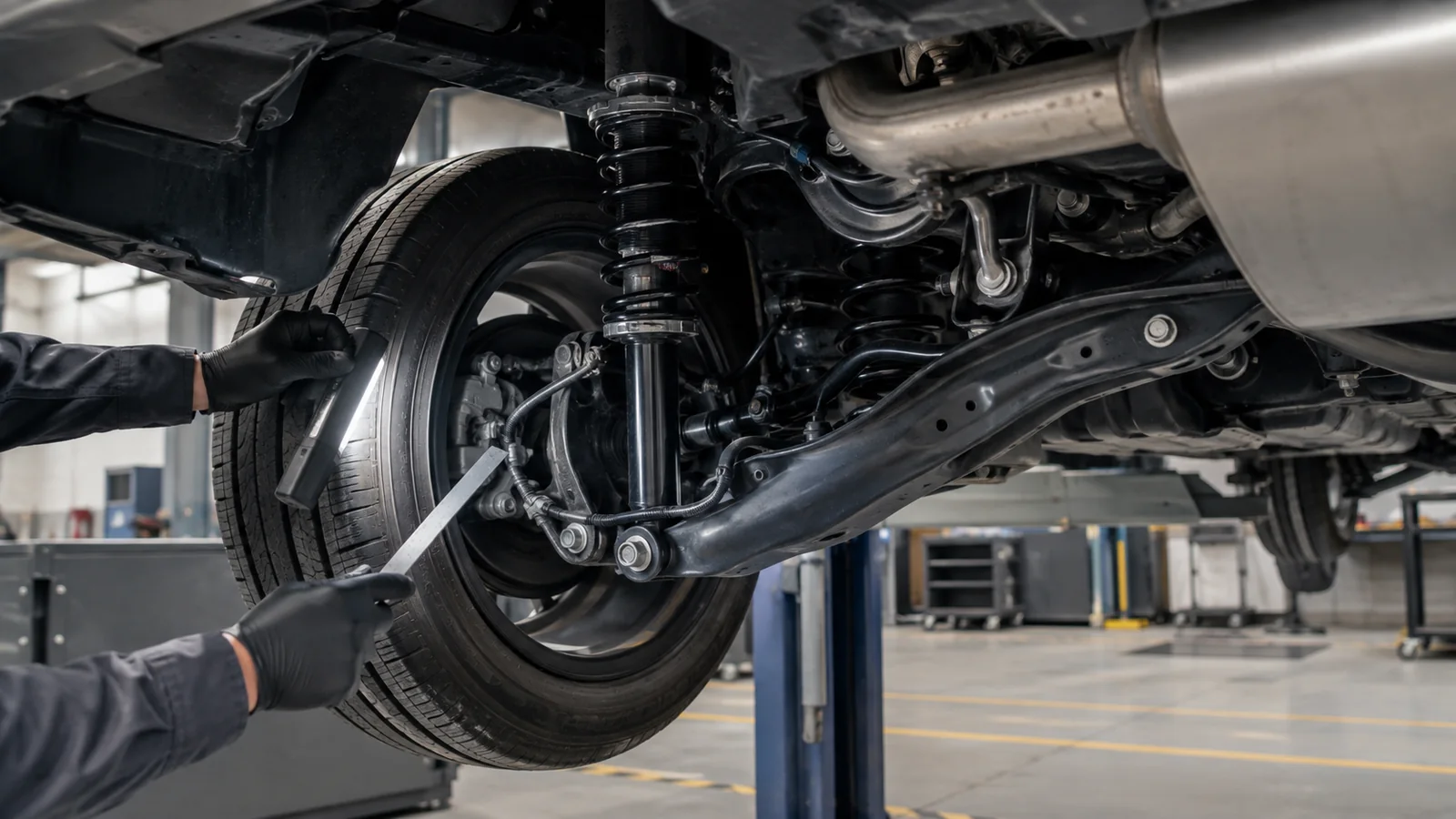
An adjustable control arm can fit correctly at static ride height and still create a clearance issue when the suspension moves.
This is particularly important on modified SUVs using larger tyres, different wheel offsets, increased or reduced ride heights, or other aftermarket suspension components.
A fitment review should therefore consider potential interaction with:
- Chassis and subframe
- Wheel and tyre
- Shock absorber or coilover
- Springs
- Brake hoses
- ABS wiring
- Driveshafts or CV components where relevant
- Other control arms and suspension links
Adjustment itself also needs to be considered.
Changing arm length or joint position can alter where the component sits relative to surrounding parts. A suitable design therefore needs to account for both the nominal installation position and the intended adjustment range.
A Typical Adjustable Control Arm Setup Decision
Consider an SUV that has received a suspension-height change and larger wheel-and-tyre package.
After the modification, the available OE alignment adjustment may no longer provide the desired geometry.
A simple response would be to install an adjustable arm with the widest possible correction range.
A more complete approach asks several additional questions.
Which alignment parameter actually requires correction?
How much additional adjustment does the vehicle need?
Does changing arm length alter tyre position or wheel-arch clearance?
Will the arm maintain clearance through steering and suspension movement?
Is the adjustment mechanism accessible when installed?
Does the joint remain within its intended operating angle?
Can the alignment be locked securely once the target position is achieved?
These questions may lead to a different product decision: rather than maximizing adjustment range, the arm is configured around a usable correction window that supports the intended vehicle setup while maintaining appropriate mechanical engagement and clearance.
That is the purpose of a vehicle-specific adjustable control arm kit.
Prototype and Fitment Review
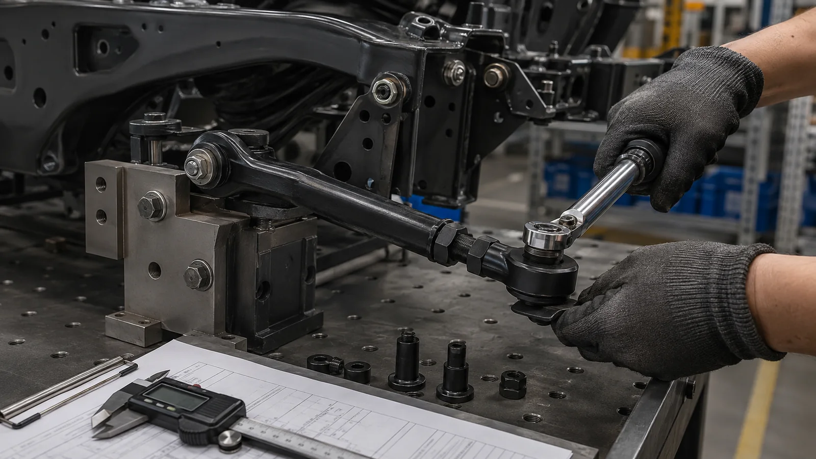
Once the proposed adjustable arm specification has been established, a prototype or pre-production component can be reviewed against the vehicle requirements.
Depending on the project scope, the review may include:
- Mounting-point verification
- Installed arm position
- Adjustment accessibility
- Usable adjustment range
- Joint articulation
- Thread engagement where applicable
- Locking mechanism
- Wheel and tyre clearance
- Chassis and subframe clearance
- Brake-line and ABS-wire clearance
- Suspension-travel clearance
- Steering clearance where relevant
- Alignment capability
- Installation requirements
The purpose of this stage is to identify conflicts before the component specification moves into repeat production.
For example, increasing the available correction may position part of the arm closer to the chassis or another suspension component.
Instead of accepting the maximum theoretical adjustment as the product specification, the usable range can be defined around the positions that maintain the required fitment and mechanical conditions.
This turns adjustment range into an engineering parameter rather than simply a marketing number.
From Fitment Review to Production Specification
Following engineering and fitment review, the final product specification defines the controlled parameters required for manufacturing.
Depending on the adjustable control arm program, this may include:
| Parameter | Production Definition |
|---|---|
| Vehicle application | Make, model and generation |
| Arm position | Front/rear and upper/lower application |
| Adjustment function | Camber, caster, toe or specified geometry correction |
| Adjustment mechanism | Project-specific design |
| Adjustment range | Defined for vehicle application |
| Joint/bushing configuration | Defined for intended use |
| Mounting interface | Vehicle-specific |
| Hardware | Application-specific |
| Material and construction | Product specification |
| Finish | Project/customer specification |
| Installation requirements | Documented for target platform |
| Inspection requirements | Defined quality criteria |
A controlled specification helps ensure that the intended geometry, fitment and adjustment characteristics are reproduced consistently during manufacturing.
Building a Vehicle-Specific Adjustable Suspension Package
An adjustable control arm should not be defined only by how far it can move a wheel alignment setting.
For SUV suspension applications, the complete product needs to balance:
- Camber, caster or toe correction
- Ride-height changes
- Adjustment range
- Joint articulation
- Mechanical engagement
- Wheel and tyre clearance
- Suspension travel
- Installation accessibility
- Locking security
- Serviceability
- Vehicle-specific fitment
The objective is to provide useful suspension geometry adjustment within the physical and mechanical requirements of the intended vehicle.
For ROOVA, this means developing adjustable suspension components around the vehicle application and desired use case rather than treating maximum adjustment as the primary product objective.
Develop an Adjustable Control Arm Kit for Your Application
ROOVA supports distributors, suspension brands and private-label aftermarket programs developing adjustable control arms and related suspension components for vehicle-specific applications.
To begin an adjustable suspension arm project, customers can provide:
- Vehicle make, model and generation
- Front or rear suspension application
- OE component or reference information
- Modified ride-height range
- Wheel and tyre specifications
- Required camber, caster or toe adjustment
- Intended street, touring, performance or mixed-road use
- Preferred joint or bushing configuration
- Product positioning and branding requirements
ROOVA can then review the application requirements around suspension geometry, adjustment, fitment, component configuration, manufacturing and production specifications.
Related Suspension Solutions
Adjustable Upper Control Arms
Vehicle-specific upper control arms developed to provide additional alignment adjustment for modified suspension applications.
Adjustable Rear Camber Arms
Adjustable suspension links for applications requiring additional rear camber correction following ride-height or suspension changes.
Adjustable Toe Arms
Vehicle-specific adjustable links for applications requiring additional toe adjustment and alignment control.
Private-Label Suspension Components
Custom suspension component development and manufacturing support for aftermarket brands, distributors and vehicle-specific product programs.
