Colección de ruedas
Ruedas. Diseñadas a tu manera.
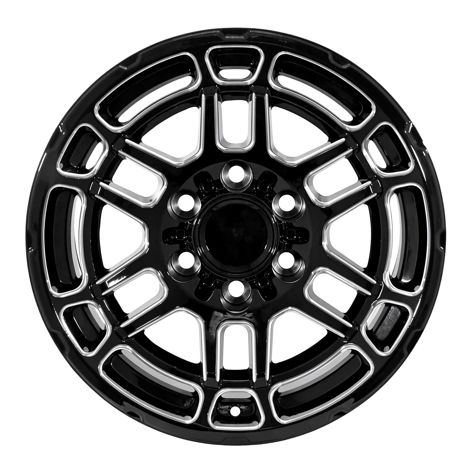
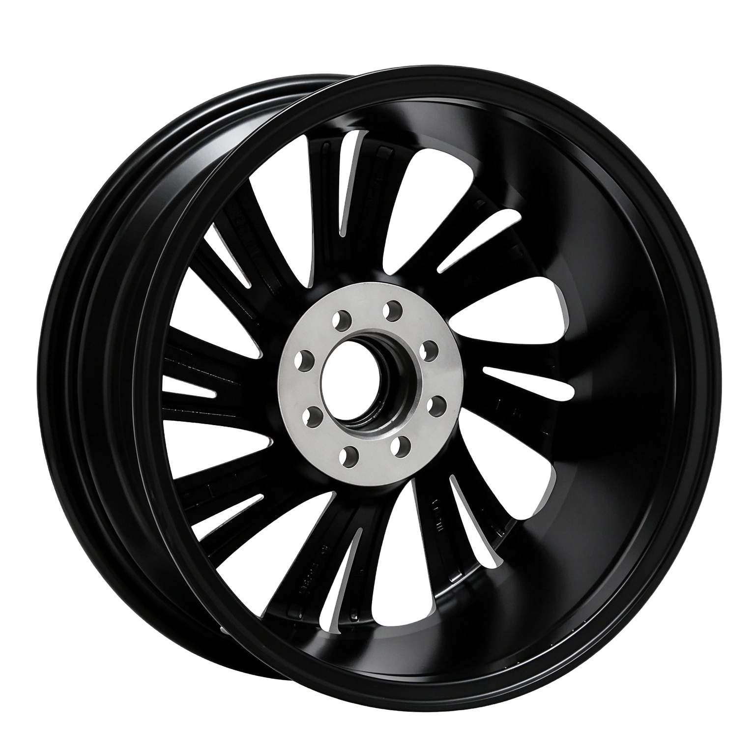
Desde ruedas forjadas de una pieza hasta configuraciones personalizadas de dos piezas, ROOVA ayuda a marcas y distribuidores a convertir un briefing de diseño en una especificación lista para producción.
Explora la gama01 / 03

01 / 03


La precisión impulsa más lejos.
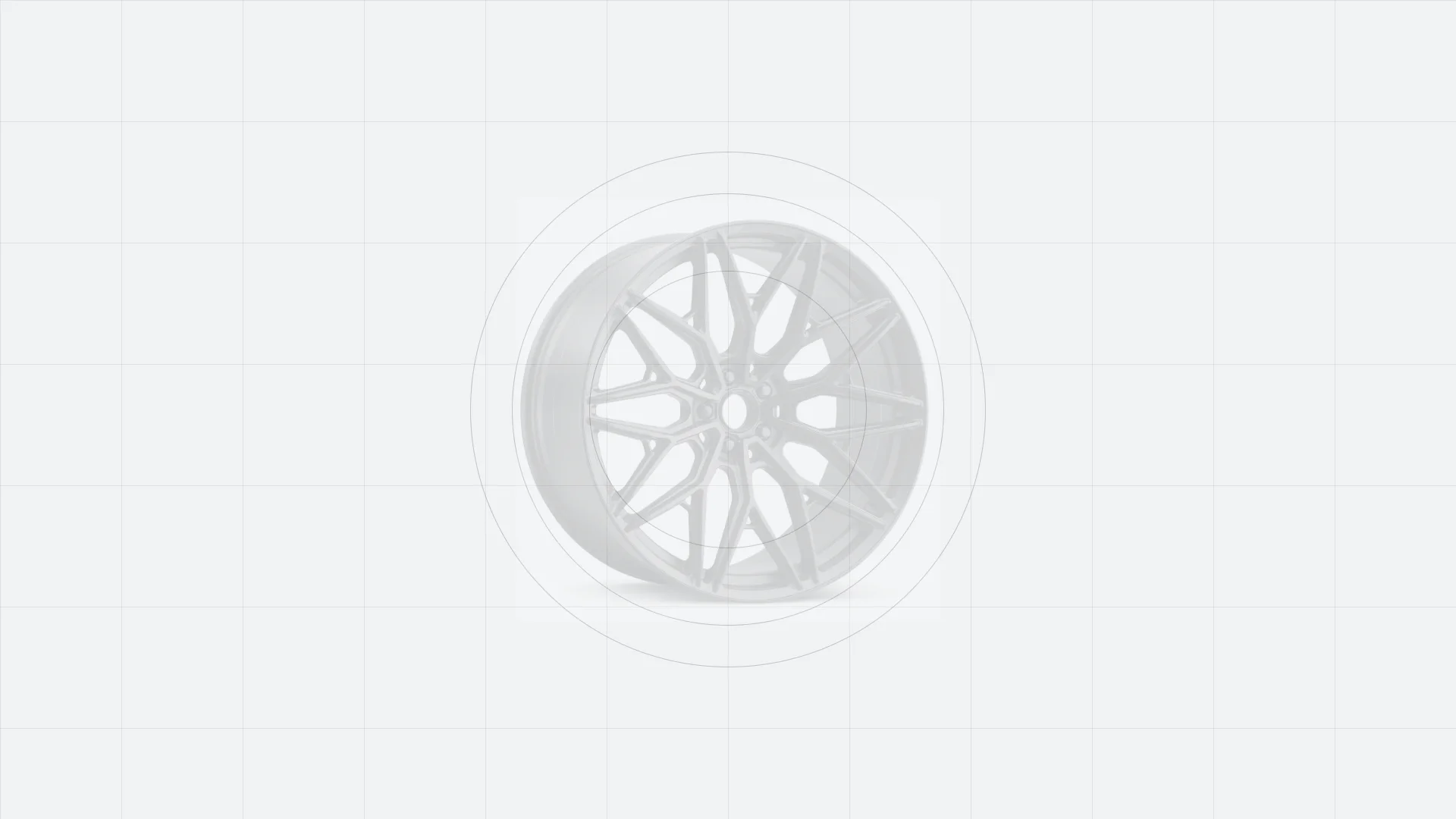
Diseño personalizado
Tu proyecto de ruedas a medida.
De la idea al rendimiento listo para la carretera, creado para tu vehículo.
 01
Elige tu estilo
Explora estilos de ruedas forjadas o comparte tu inspiración.
 02
Confirma las especificaciones
Confirma tamaño, PCD, offset, diámetro central y acabado.
 03
Recibe tu diseño
ROOVA prepara un plano detallado de la rueda para tu aprobación.
 04
Fabricación de precisión
Tus ruedas a medida se mecanizan por CNC y se someten a controles de calidad.
 05
Entrega mundial
Embalaje seguro y envío internacional hasta tu destino.
Fabricación controlada
Producción proceso.
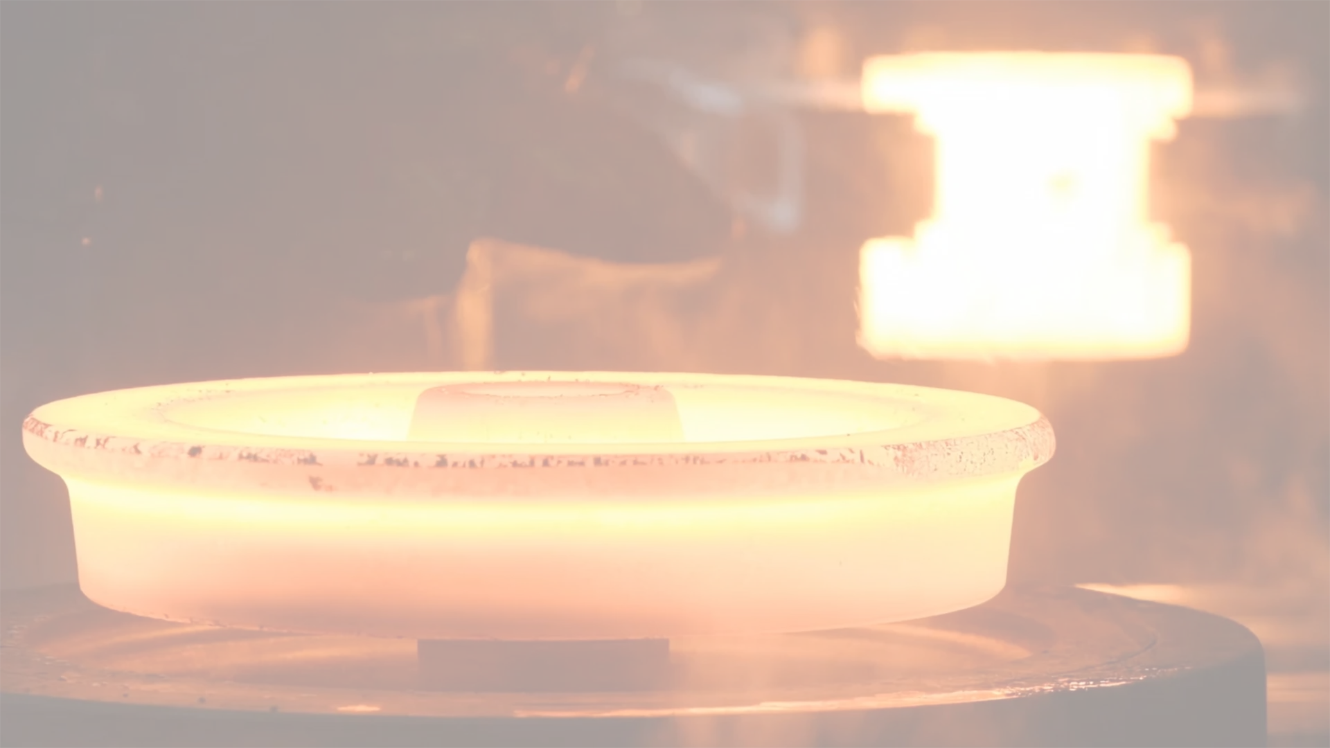
FORGING
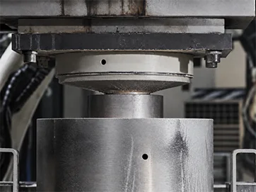
Cada rueda comienza como un bloque macizo de aleación de aluminio. El bloque se coloca en una prensa de forja y se comprime bajo una enorme presión que compacta la estructura granular del metal: su densidad molecular aumenta y se distribuye de manera uniforme en un área mucho mayor. Así, el material gana resistencia y capacidad de absorción de impactos mientras reduce peso, y el contorno básico del disco ya toma forma.
FLOW FORMING
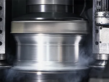
La pieza forjada sale de la prensa como un disco plano, pero una rueda también necesita su sección exterior: la llanta. Una máquina de flow forming sujeta el borde del disco y lo desplaza hacia fuera bajo presión, estirando el metal hasta formar un cilindro hueco. Como la llanta se comprime una segunda vez en esta etapa, su densidad aumenta de nuevo y la rueda terminada resulta notablemente más resistente.
HEAT TREATMENT
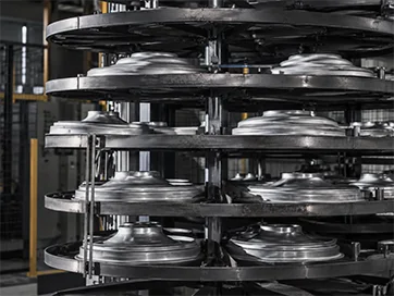
A continuación, la rueda pasa por un ciclo de tratamiento térmico a temperaturas de entre 200 y 500 grados Celsius. Esto redistribuye la estructura interna del metal para hacerla más uniforme y estable, relajando las tensiones internas dejadas por la forja y el trabajo en frío. Se recupera la elasticidad y aumentan tanto la resistencia de la aleación de aluminio como su resistencia a los impactos.
LATHE CUTTING
En el torno, las herramientas de corte trabajan las superficies de la llanta hasta sus dimensiones finales. Se retira material de la zona de la llanta para darle el perfil definido por el diseño y situar cada dimensión crítica dentro de las tolerancias exigidas por la especificación.

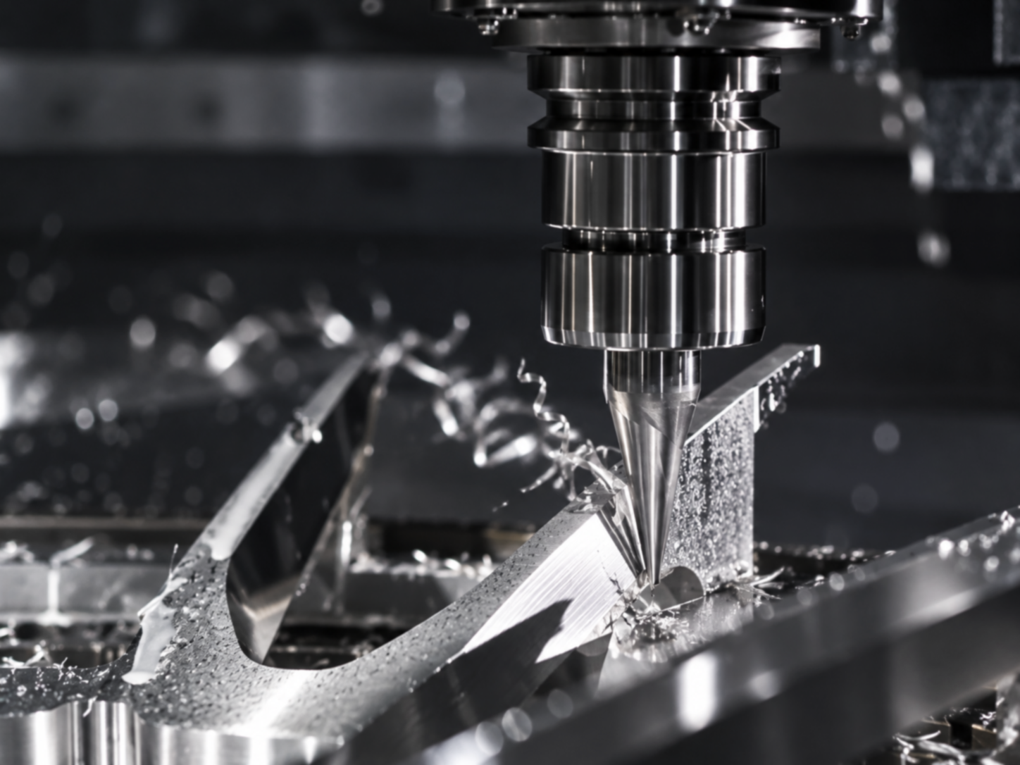
MILLING
Milling gives the disc its finished appearance: the number of spokes and the fine detailing of the wheel design are all cut at this stage, exactly as defined in the approved drawing. A one-piece (monoblock) design demands a greater cutting volume and deeper tool travel, so these programmes are run on more capable equipment such as a 4-axis or 5-axis milling machine.
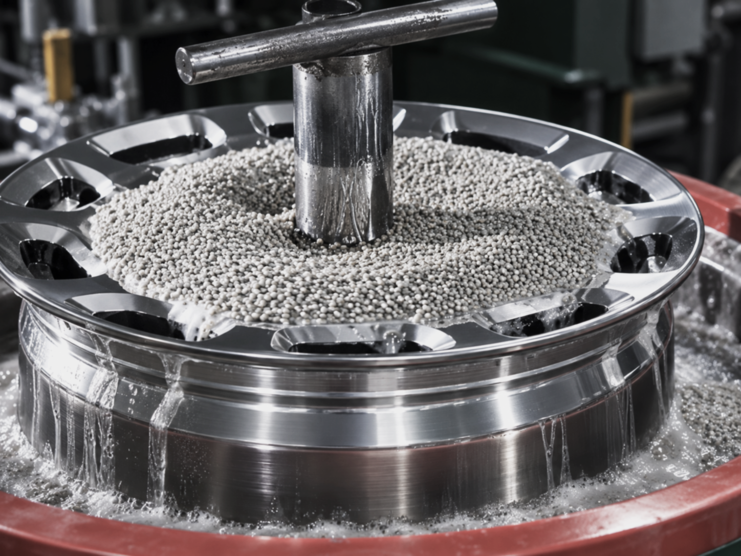
GRINDING AND POLISHING
Once the wheels have been painted, they are ground and polished to bring out the full depth and perfection of the paint finish. The same stage is also used to verify the quality of the spray work. Every wheel is inspected continuously along the way, which is what allows each one to reach the customer in the best possible condition.
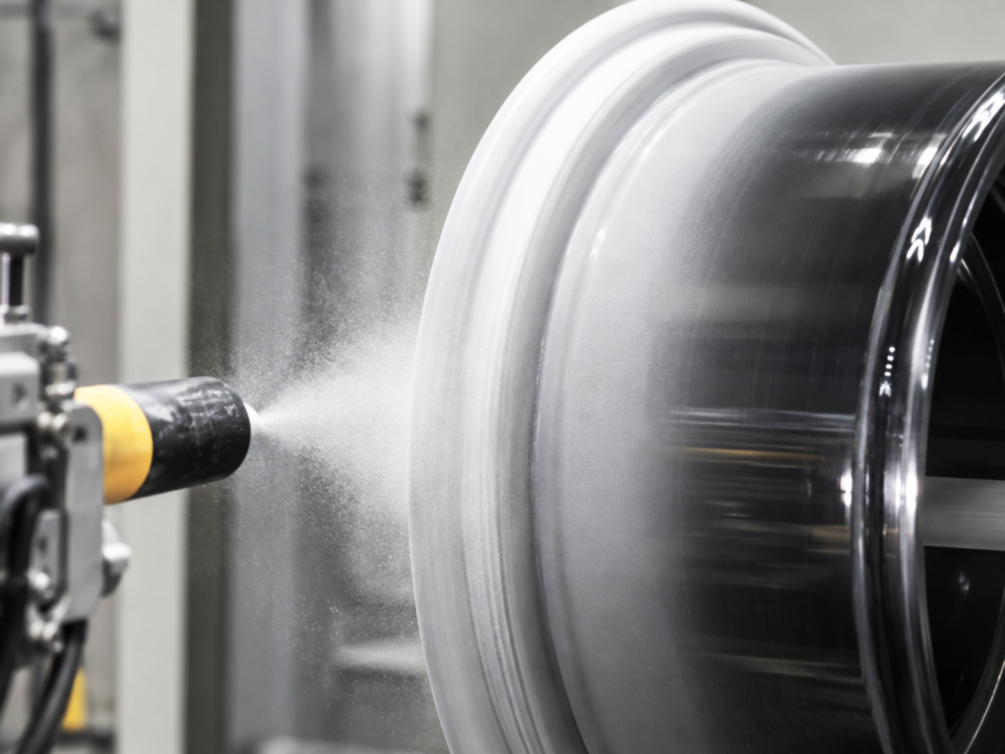
PAINTING, ASSEMBLY
Final assembly takes place in this area: fitting the valve stem, mounting the centre cap, and joining the halves of a two-piece wheel. Every screw on a two-piece wheel is tightened by hand with the help of a torque wrench, so that all of them carry an identical load and none is overlooked. Each fastener is then marked so that any loosening can be spotted during later inspection, and the torque wrenches themselves are recalibrated on a regular schedule.
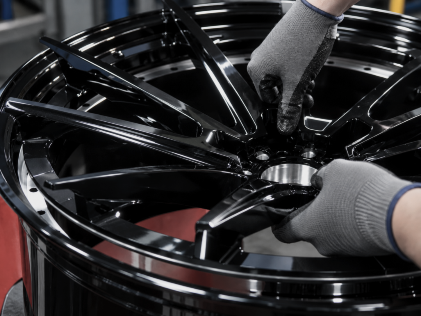
PACKAGING AND ASSEMBLY
With manufacturing complete, the wheel moves to packing and dispatch. The first step is to cover the face of the disc with a protective cloth, which keeps the surface free from damage in transit. Cushioning material is then placed inside the box, since proper shock absorption in the carton is what ultimately protects the wheel on its journey.
RADIAL FATIGUE TEST
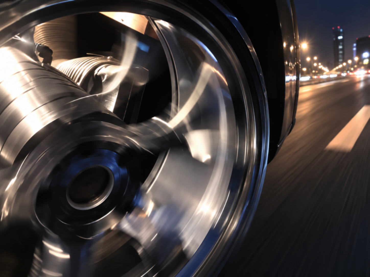
This test measures how well a wheel stands up to heavy loads applied in the radial direction, and whether repeated loading eventually causes metal fatigue. It runs on a test rig that reproduces the way a wheel rotates on an ordinary road surface.
WHEEL CORNERING FATIGUE TEST
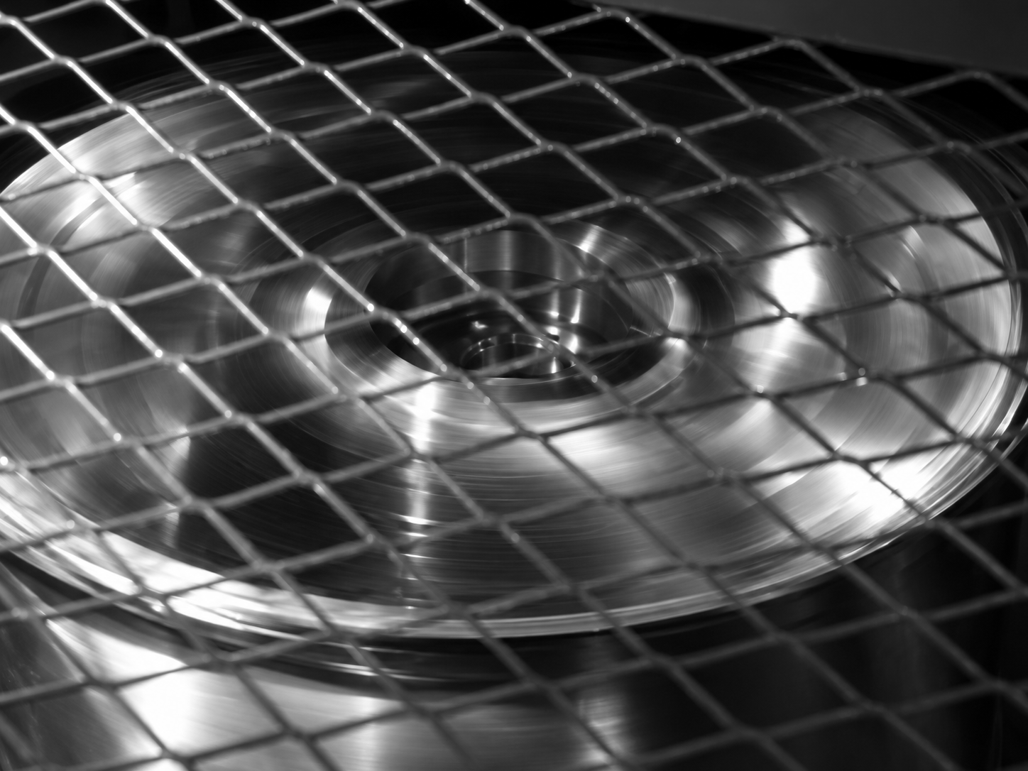
Here the load is applied from the side rather than the top, establishing how much lateral force the wheel can carry before repeated cycles begin to fatigue the metal. As with the radial test, the equipment simulates a wheel turning on an ordinary road surface.
IMPACT TEST MACHINE
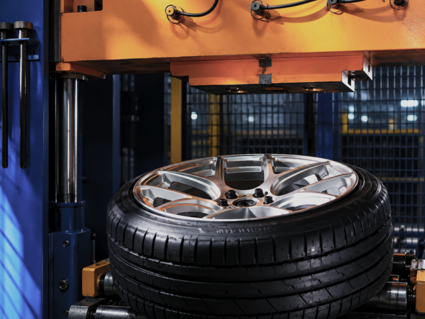
The impact rig reproduces the conditions a wheel meets on the road and assesses how it copes with a sudden blow, such as striking a pothole or a kerb. Any crack running through the material, or any loss of tyre pressure caused by the impact, is recorded during the test.
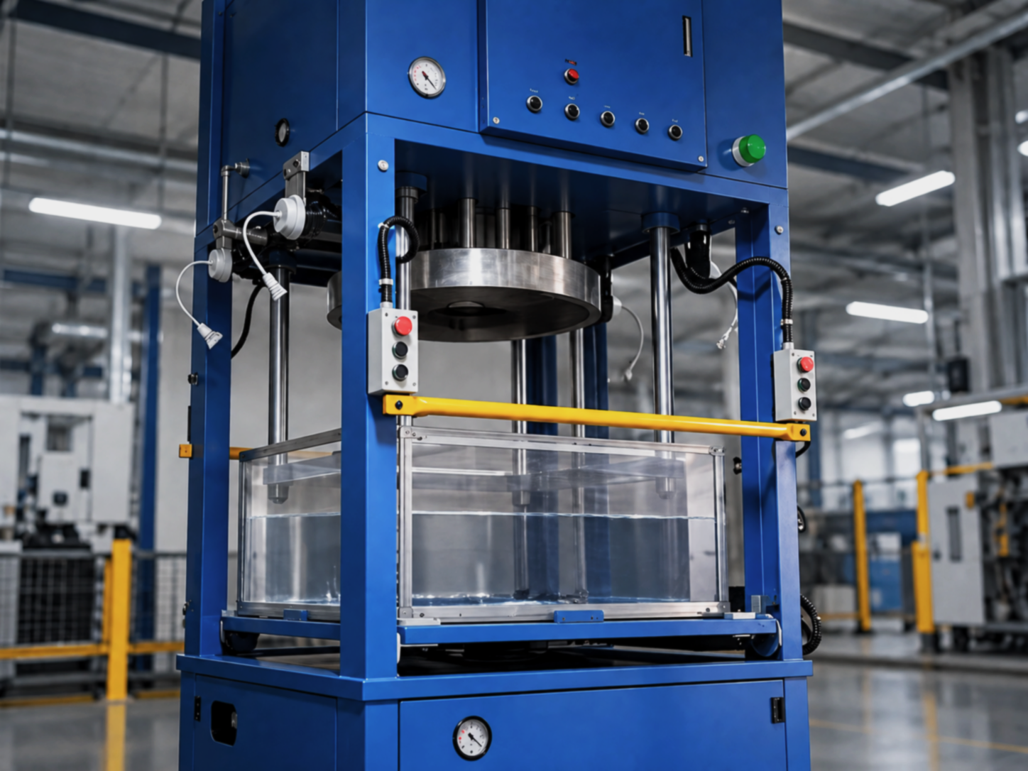
IMMERSION LEAK TEST MACHINE
This test exists to catch any air leak around the valve stem. The wheel is lowered into a water tank while high pressure air is fed through the valve, and the water surface is watched closely: any escaping bubble immediately reveals a leak.